

Construction
In the execution of this project, three pivotal manufacturing methods—3D printing, machining, and sendcutsend—have been strategically employed. The preeminent technique is 3D printing, where meticulous layers of melted plastic are precisely extruded to form the desired components. Simultaneously, machining is utilized to extract metal from solid stock using sharp tools affixed to state-of-the-art machines such as lathe, CNC, Mill, and Band Saw.
While the majority of parts are crafted through 3D printing for their adaptability in creating intricate geometries, the chassis, a pivotal element in the project's architecture, was machined in-house with the possibility of outsourcing it through sendcutsend if complications occurred during the manufacturing process. This decision was rooted in their unparalleled waterjet precision and efficiency in intricately cutting designs from sheet metal. The chassis, being a linchpin in the project, demanded meticulous cuts and precise shaping, making Sendcutsend's waterjet technology the optimum choice. This multifaceted approach, blending 3D printing, machining, and specialized outsourcing, underscores the project's commitment to achieving an unparalleled level of precision, efficiency, and robust functionality in the final product.

Figure 1- Mill Machine
The left-side image captures the student engaged in milling machine operations, skillfully trimming the stock to precise dimensions. This preparation is crucial for subsequent CNC processing to ensure accurate final dimensions. Although the student received an introduction to milling machine operation during their freshman year, this project marks a significant opportunity for the student to dive deeper into the intricacies of utilizing the milling machine to manufacture a part. Prior exposure laid the groundwork, but it is through this project that the student gains a comprehensive understanding and practical experience in leveraging the milling machine for effective part production.

The image on the right depicts the student using the CNC machine to cut out their part, following the initial step of drilling holes with the mill machine shown above. Austin Taylor, a fellow student overseeing the machine shop, assisted them by programming the necessary code for cutting the part and setting up the machine. The student lacked familiarity with the machine's operation, so Taylor's guidance was invaluable. With Taylor's help, the student received a refresher on operating the machine, drawing on their previous experience from a class taken in their junior year.
Figure 2- CNC Machine

The image on the left portrays the student operating a Mill machine to precisely mill a section on the trailing arm tabs. This modification allows the trailing arm to smoothly slide through and securely attach to the chassis, as this is the designated point for bolting this component. This meticulous adjustment ensures proper alignment and attachment, thereby enhancing the structural integrity and functionality of the assembly.
Figure 3- Mill Machine
The image on the right showcases the student's utilization of the lathe machine to craft a bushing, which will undergo a press-fit onto a bearing. Subsequently, this bushing will be press-fitted onto the bevel gear, ultimately situated on the rear axle housing. This meticulous process ensures the seamless integration of components, enhancing the overall functionality and stability of the mechanism.
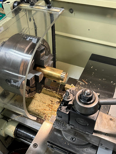
Figure 4- Lathe Machine
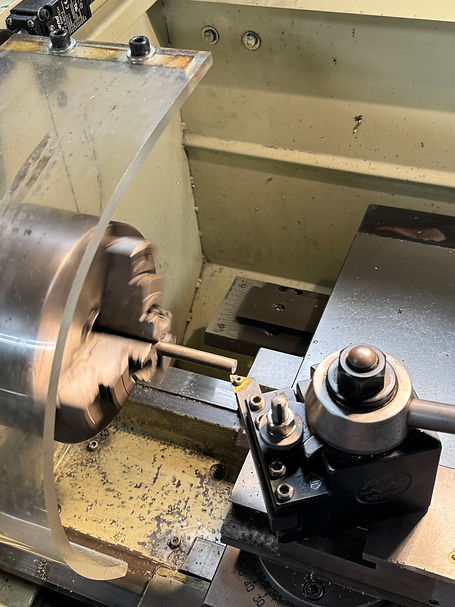
The image on the left illustrates the student operating the lathe machine to precisely shape a section of the rear axle to the correct diameter, facilitating the creation of a threaded surface for a 4mm bolt. This bolt will serve to secure the tires firmly onto the axle, ensuring proper assembly and functionality.
Figure 5- Lathe Machine
The video on the right demonstrates the student utilizing a horizontal band saw to make precise cuts on an axle, ensuring it meets the necessary length specifications. Subsequently, the axle will undergo machining on the lathe machine to achieve the desired diameter, enabling it to be press-fitted onto the gear mount. This meticulous machining process guarantees that the axle is custom-fitted to seamlessly integrate into its designated position, thereby bolstering the stability and operational efficiency of the gear assembly.
Figure 6- Horizontal Band Saw
Drawing Tree

Figure 7- Drawing Tree